
For controlling DC motor speed, often the PWM method is used. Using this method you can accelerate or decelerate the motor speed, but without any feedback, the speed of the motor strongly depends on the conditions, like the motor load, or the voltage source.
If you want to know the exact speed of the motor, you can use a feedback device (e.g. an encoder). With information from the feedback device, you can adjust the duty cycle of the PWM signal to keep the motor at the desired speed.
In this article I would like to show how the DC motor speed can be measured without using any external feedback device. Take a look at the schematic below. It’s a standard circuit for a PWM controlled DC motor.
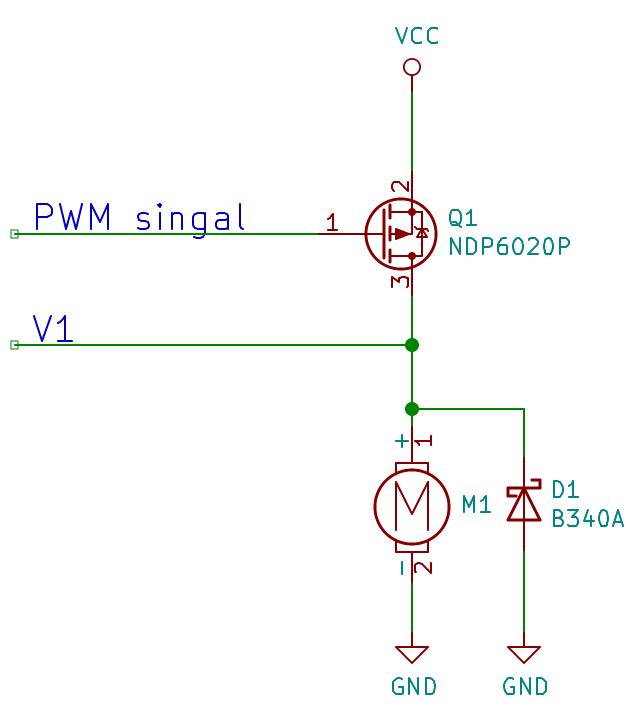
Now let’s turn it on and measure the voltage at V1 point.
PWM period is 16.386 ms, and duty is set to about 50%.

During the entire cycle of the PWM modulation there are short pulses which are quite interesting, but we’ll get to them later. Now let’s focus on the “off” time. During the off time there is a small periodic waveform. Let’s call it an “off waveform”.
This waveform is created by rotor windings that are moving through magnetic field of stator magnets. I don’t want to get through details of a DC motor construction, but in general, this waveform’s period is the 1/6th of the of the full DC motor period (full revolution), so we can use this waveform to measure the real speed of the motor.
I built a small device using PIC16F1619 microcontroller with the Curiosity board to regulate the motor speed using this method as a feedback signal. I have chosen this microcontroller because it has a lot of peripherals that helped me with such a measurement. For this purpose I could also use those short voltage peaks, but their width is too short to be measured using this microcontroller (or at least I didn’t succeeded in the first few tries).
Here’s the “schematic” of the device.

And here’s the picture:
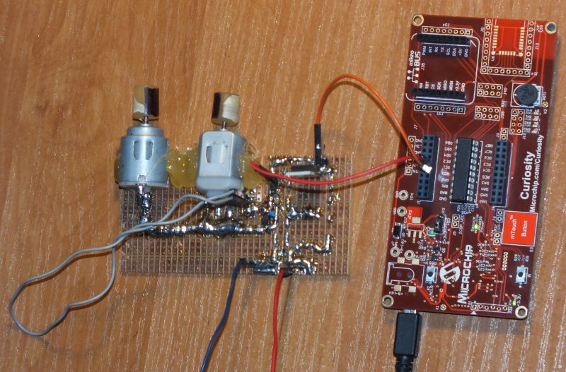
I have two different DC motors, to make sure that using this method I can regulate the motor speed regardless of the motor type. Cylinders (made from a glue stick) are mounted on each of the motors shafts. I marked one side of the cylinder with a black marker and the other side with a white tape for the speed measurement. The speed measurement was taken by the CNY70 reflective sensor connected to an oscilloscope, as on the schematic below.


This sensor is used just to make the independent measurement of the speed and it’s not a part of the speed regulation system. It’s powered up from the curiosity board but the output signal goes just to the oscilloscope.
The MPLAB project for this device is available in the github repository:
https://github.com/kryzysoft/DCMot_mplab.git
You can check the configuration in the project. Here I just put some general information about used peripherals:
TIM2 and PWM3 – for PWM signal generation
CLC1, TIM0 and ADC – for measuring the average value of the waveform (TIM0 for triggering ADC). CLC1 is used to make sure that the average value will be measured only during the “off” time of the PWM.
DAC – for generating the reference voltage (which will be equal to the average value of the waveform during the off stage) for the comparator
CMP1 – for generation of the square signal from the “off” time waveform. Measuring the period of the square waveform is easier than of the analog waveform
SMT1 – a signal measurement timer – for measuring the period of the CMP1 output (which will be equal to the waveform period)
CLC3 – is used only for the interrupt generation on the both edges of the PWM signal (to make some calculations at these points).
MATHACC – is used to regulate the motor speed. It’s configured to the PID regulator mode. The measured period of the waveform is used as the feedback input of the PID regulator. The output of PID regulator will be the PWM duty cycle.
Let’s run the experiment. CNY70 sensor is positioned manually, close to the rotating cylinder, like in the picture:

The sensor output signal for the first motor:

The sensor output signal for the second motor:

Both measurements were made with the same firmware and the same configuration. PID regulator is configured to keep the “off waveform” to have period of 2 ms. As you can see in the both oscillograms, the period of full revolution of the motor was 12 ms (as we expected 6 x 2 ms). Without using any external feedback device we are able to keep the speed of the motor constant.
The most important advantage of this method is that there is no need for any other mechanical feedback components. But there are also some disadvantages. We can measure the speed of the motor only if the “off” time of the PWM signal is long enough. It has to be at least 2 times longer than the 1/6th of the period of full motor revolution. So if the PWM duty cycle is too high, or the motor speed is too low, we won’t have a good feedback signal.