
Hello everyone!
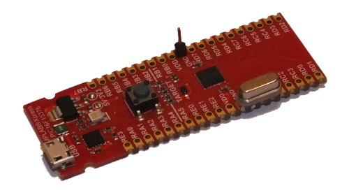
This week I get evaluation board from Microchip:
MPLAB Xpress PIC16F15376

I’m not familiar with Microchip microcontrollers. I heard about really interesting peripheral they have: NCO – Numerically Controlled Oscillator (as far as i know that’s the only microcontroller manufacturer that have something like this). It’s oscillator with linearly controlled frequency.
Usually when you want to generate rectangular waveform of given frequency in microcontroller you have to divide some internal clock frequency by integer factor using standard peripheral like timer.
When you have microcontroller that have internal frequency of 10 MHz, you can divide it by 2 to get 5 MHz, or divide it by 3 to get 3.333 MHz, or by 4 to get 2.5 MHz signal, etc. But the problem is that you cannot get 9.9 MHz just by dividing the main frequency. The frequency of internal clock have to be divisible by the expected output frequency.
Let’s assume that we want to have system that is capable of generating rectangular signal of 10 MHz and we want to change it to 9.9 MHz. Lets make some calculations. The difference in period of 9.9 MHz and 10 MHz signal is:
\(\large \Delta T = \frac{1}{9.9\: \mathrm{MHz}}-\frac{1}{10\: \mathrm{MHz}}= 1.0101 \: \mathrm{ns}\)
So if we want to generate two signals which difference in period is 1.0101 ns, we should have internal clock of period that is equal or less than 1,0101 ns. The minimum clock frequency in that case should be:
\(\large f_{int} = \frac{1}{\Delta T}=990 \: \mathrm{MHz} !!!\)
According to datasheet of PIC16F15376 the NCO is capable of generating any frequency from 0 to 32 MHz with resolution of:
\(\large \Delta f = \frac{32\: \mathrm{MHz}}{2^{20}} \approx 30 \: \mathrm{Hz} \)
Resolution of 30 Hz is far more precise than resolution required in our example (900 kHz).
Is it possible to create clock signal of 10 MHz and 9.9 MHz in microcontroller which maximum internal frequency is 32 MHz?
Lets check it.
To make measurement more precise, I decided to connect external 8 MHz crystal oscillator (to pins RA7 and RA6), and use it as clock source. 12 pF capacitors are on bottom side. I also put goldpin on GND to connect GND wire from oscilloscope.
I used MPLAB X IDE which have great tool called MCC (MPLAB Code Configurator). It takes me just few minutes to configure system clock, NCO, and port RA0 as output of NCO.
System module configuration: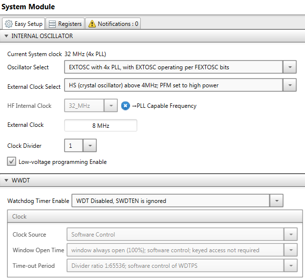
NCO configuration: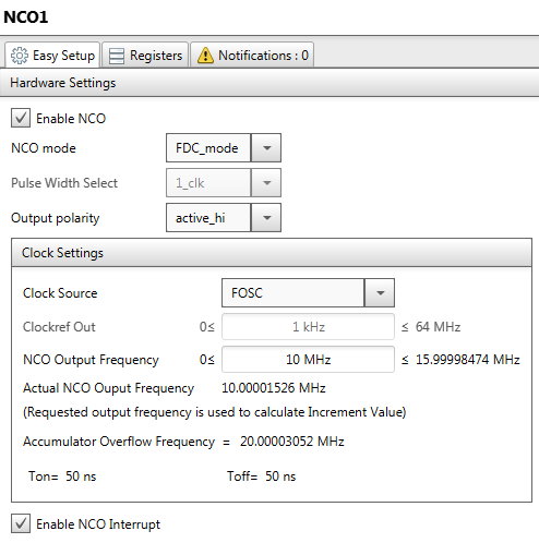
Ports configuration: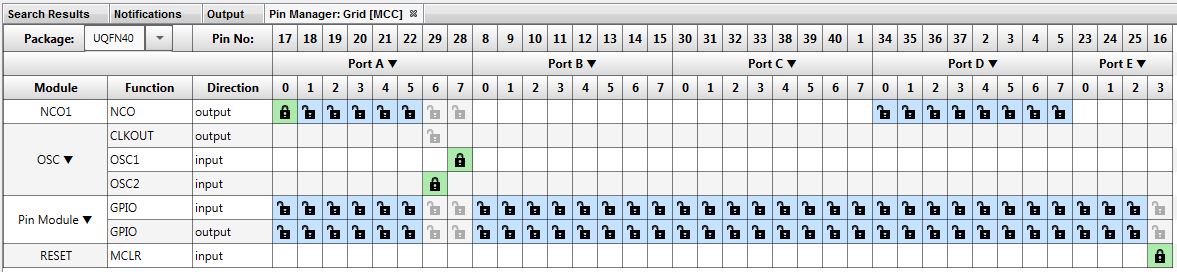
I also have to slightly change the main function (actually I had to create it), because at default configuration, the slew rate control of port A is disabled, so I couldn’t get the output frequency on that port high enough.
The main function of the project is presented below.
void main(void) {
    SYSTEM_Initialize();    // Initialization function from MCC
    SLRCONA = 0x00;         // High slew rate
    while(1)
    {
        CLRWDT();           // Clear watchdog timer
    }
}
Here is what i get on output of NCO when i configure NCO to 10 MHz:
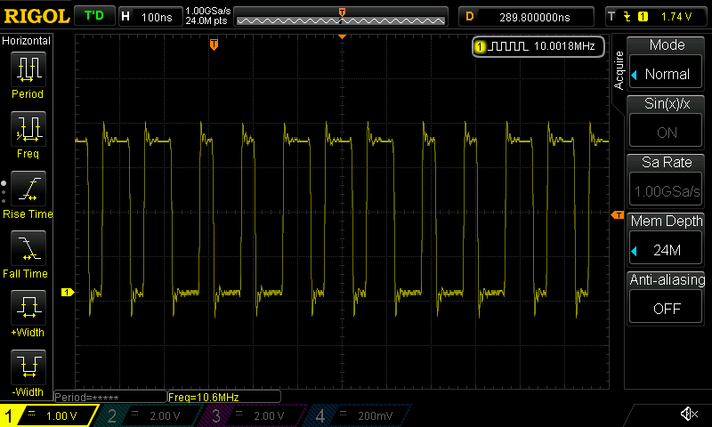
As you see, the period of signal is not constant. We see two different periods and duty cycles of rectangular signal which are multipliers of 31,25 ns. The period and duty cycle of generated signal is changing in the way that average frequency of signal in long term is 10 MHz (the frequency of signal is in upper right corner of oscilloscope screen). This kind of signal can be created from the system clock frequency of microcontroller (32 MHz) so there is no magic in NCO. Just to finish my measurements i changed the configuration of NCO to 9,9 MHz and also get the screen form oscilloscope.
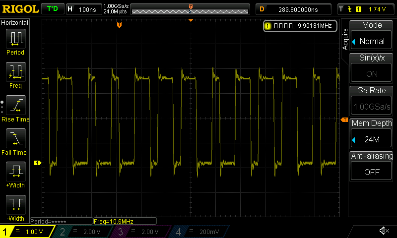
Again we get the periods and duty cycles that are multipliers of 31,25 ns which is period of system clock frequency 32 MHz, and the average output frequency is what we wanted: 9.9 MHz
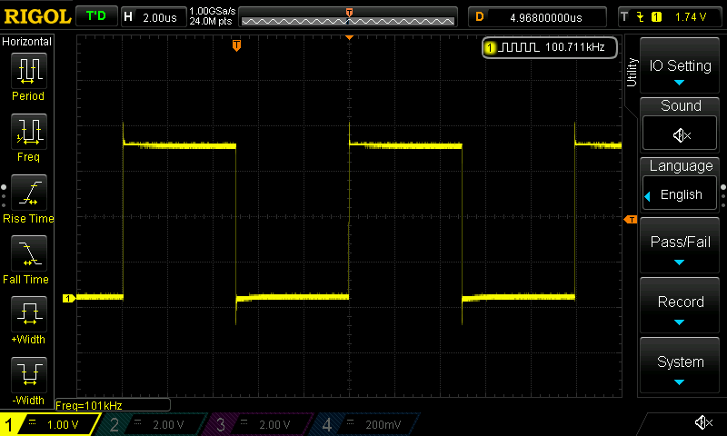
Of course if we want to generate signal with lower frequency, the effect won’t be noticeable. In next picture there is the same example but with changed frequency to 100kHz.
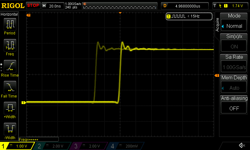
If we magnify the rising edge (the trigger of oscilloscope is set to falling edge), we will see that duty cycle still changes by 31,25 ns, but when we compare it to total period of signal it really doesn’t matter.
Conclusion
The Numerically Controlled Oscillator is capable of generating signal with linear range of frequencies, but it’s worth noting, that the frequency we are talking about is average frequency in long term. In short term we get rectangular signal of period and duty cycle which are multipliers of system clock period. Of course if we want to generate signal with lower frequency, that effect won’t be noticeable. Anyway NCO is very useful peripheral and it cannot be found in another microcontroller from other manufacturers (as far as I know).
Thanks to Microchip for sending me this eval board for free :).