
Hello.
When I’m using the ADC in my design I have to set proper sampling frequency. It’s usually well described in datasheet of used microcontroller (or datasheet of external ADC) how to set the sampling rate, but I always want to confirm my calculation.
One time I connect some generator with known frequency to my ADC input and analize the samples. But sometimes it’s not practical way to do it. For example when you have op amp output connected to ADC input you would have to somehow disconnect output of op amp (cutting wire or desolder opamp) and connect the generator there.
Better way is to put some code to toggle state of one pin on microcontroller in sampling complete interrupt function.
But there’s also easier way!
To demonstrate easier way, I created one project on
NUCLEO-L476RG
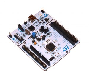
This board I get from ST on Embedded World Exhibition in Nuremberg. I’m not sure if it was this year or last year… never mind. Board is equipped with STM32L476RG microcontroller form ST company. It has ARDUINO compatible connector which I will use.
I connected the 1.65 V to ADC input by using resistor divider (two 100 Ω resistors). This divider is showed on image below.

ST have nice tool for quick code generation on STM32 microcontrollers, called STM32CubeMX. Using this generator I created simple application that runs ADC. Just runs ADC. I don’t care about sample values right now.
I configured A0 pin of ARDUINO connector (pin PA0 of microcontroller) to ADC input (ADC1_IN5). The ADC clock is set to 80 MHz (it is connected to system clock). ADC is configured to continuous conversion mode with 12 bit resolution. I set sampling time on channel 5 to minimum allowable value which is 2.5 ADC clock cycles.
Just to make sure our that our measurement works, I made some calculations. The sampling time in this configuration should be:
\(T_{SMPL} = 2.5 \cdot T_{ADC\_CLK} = 2.5 \cdot \frac{1}{80\:\mathrm{MHz}}=31.25\:\mathrm{ns}\)
According to datasheet for 12 bit resolution, conversion takes 12.5 cycles of ADC clock. So our conversion time is:
\(T_{SAR} = 12.5 \cdot T_{ADC\_CLK} = 12.5 \cdot \frac{1}{80\:\mathrm{MHz}}=156.25\:\mathrm{ns}\)
In continuous conversion mode, the ADC starts new sampling right after end of previous conversion, so sampling frequency should be:
\(f_{S} = \frac{1}{T_{SMPL}+T_{SAR}} =5.33\:\mathrm{MHz}\)
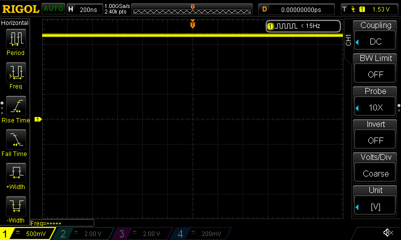
Then I connected the oscilloscope probe on ADC input. First picture shows the waveform on ADC input when ADC is off.
Now let’s turn on ADC.
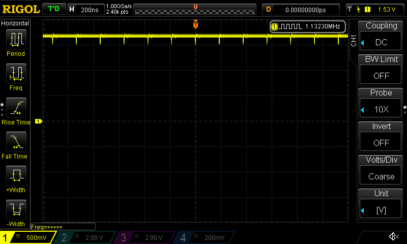
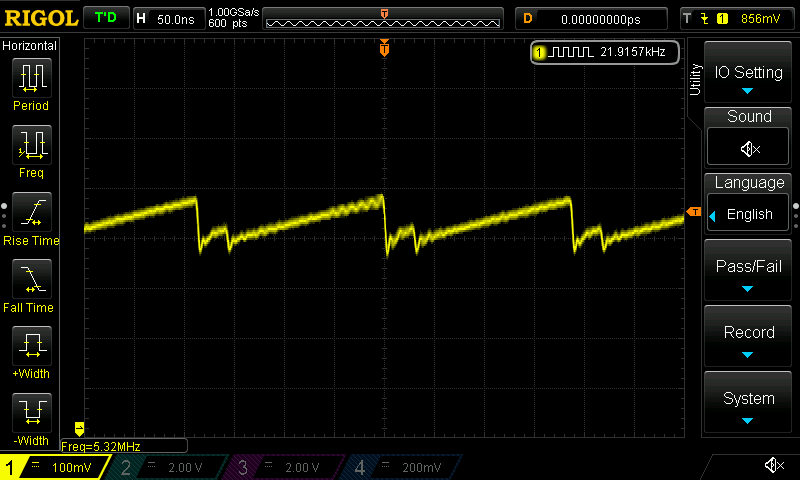
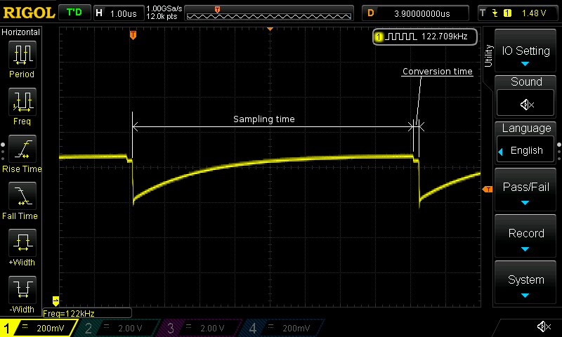
As you see there is some peaks on the waveform. You know what’s the frequency of those peak is? It’s 5.33 MHz! It’s the sampling frequency we calculated before! The peaks are caused by charging internal capacitor of sampling and hold circuit. Another interesting thing we can see when we take a closer look on that waveform.

We can see the connecting and disconnecting ADC sample and hold capacitor. From this waveform we can get the sampling time which is close to our calculated value (31.25 ns). We can also get the conversion time if ADC starts new sampling right after end of previous conversion which is also close to calculated value (156.25 ns). We didn’t needed to make those calculations. We could just set up our project, and measure sampling and conversion time by oscilloscope.
There is also one more interesting thing that we can quick check. When we are connecting some high resistance source to input of ADC we should check if the sampling time is long enough. Next screen shows the waveform on resistor divider with when I used resistances of 110 kΩ.
As we see, the internal sample and hold capacitor is not fully charged during sampling period, so we not get the right value after conversion. During conversion time, there is also some charging going on, but it’s probably just charging of internal capacitances of pin (i think). But anyway according to this picture we can see that sampling time should be increased to let the internal capacitor be fully charged.
I increased sampling time to 640.5 cycles and again take a look at input waveform. This time sampling time is far longer than conversion time. As we see the conversion time hasn’t changed (it’s still 2.5 cycles of ADC clock).
Now the internal capacitor is almost fully charged during the sampling period. We already set the maximum cycles count for sampling in our microcontroller. To increase sampling time we can only decrease ADC clock by dividing it. Well I won’t show you another waveform but you can guess that after decreasing the ADC clock frequency the sampling time will be increased and this time conversion time will be increased too, because it takes 2.5 cycles of slower ADC clock.
Conclusion
Just by looking at input of ADC by oscilloscope probe we can get a lot of useful information like sampling time, conversion time, sampling rate. Also we can diagnose too short sampling time for too high output resistance of signal source. It’s quite easy when we have signal of low frequency, but in high frequency signals it’s also possible (you just have to play a bit with trigger of your oscilloscope).
It’s also possible when you are using the signal sources with very low output impedance. The peak level are lower but still noticeable.
I checked this method only on SAR ADCs. On other types it may not work, as they don’t have sample and hold circuit.
Thanks to ST for sharing with me that board.