
Recently I found this:
https://cmaiolino.wordpress.com/
It’s a C64 emulator for Raspberry Pi. I have one unused Raspberry Pi Zero W, so I decided to run this emulator on it. It was working fine, but still I was missing something. To fully enjoy the experience of C64 I wanted to have some kind of an old style joystick. There are some arcade joysticks on the market, but quite large, with a lot of buttons. The C64 joystick usually had one FIRE. That’s why I decided to make my own one.

The set of joysticks includes:
- ArcJoy (arcade joystick) x 2
- ArcBase (NRF52840-DONGLE with special firmware) x 1
If you are interested in making the set, get ready for some electronic, programming and mechanical work.
Here I have all resource files:
https://github.com/kryzysoft/ArcJoy
A) Buy all components
BOM is available here:
https://github.com/kryzysoft/ArcJoy/raw/master/ArcJoy_Bom/ArcJoy_Bom.pdf
Most interesting parts:
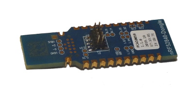
NRF52840-DONGLE – it’s a USB dongle from Nordic Semiconductor.
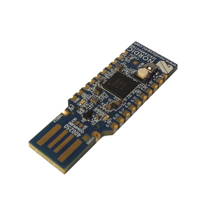
I changed its firmware to make it work as two USB joysticks and receive the joystick state from ArcJoys. Description how to do it is written down below.
BM832A – it’s a module with the Nordic Semiconductors microcontroller nRF52810.
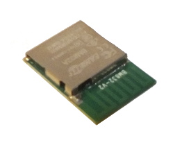
I decided to use the module instead of using just a microcontroller, because I didn’t wanted to play with designing the PCB antenna. The module comes in a BGA case, so I needed to play a bit with soldering it to the target PCB, but it’s not as hard as I thought. If you decide to make one and don’t know if you can, just watch some youtube tutorials and you’ll be fine.
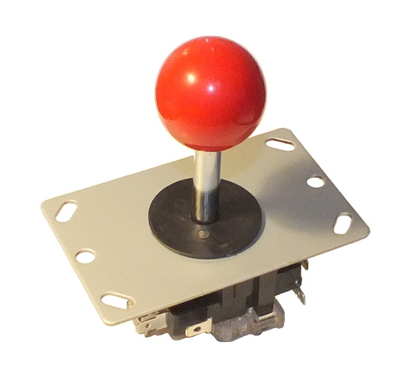
Arcade joystick – I bought it from some Chinese internet shop
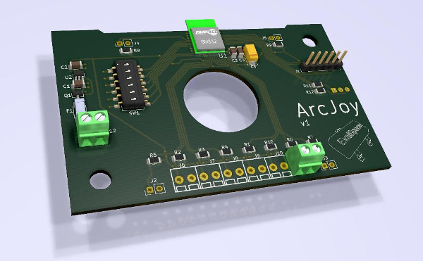
B) Prepare PCBs for ArcJoy
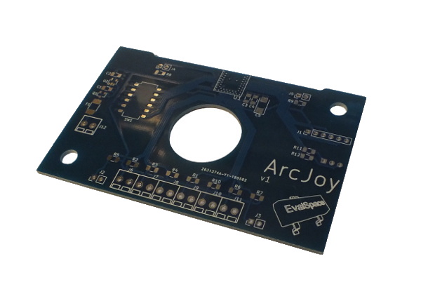
Here’s the KiCad project for this board:
https://github.com/kryzysoft/ArcJoy/tree/master/ArcJoy_Pcb
If you want to have set of two joysticks, then of course you should manufacture two boards. But if you want, one is enough. You don’t even have to have KiCad. Gerber files are generated and ready for download from github
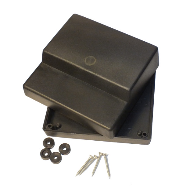
E) Prepare the case for the joystick
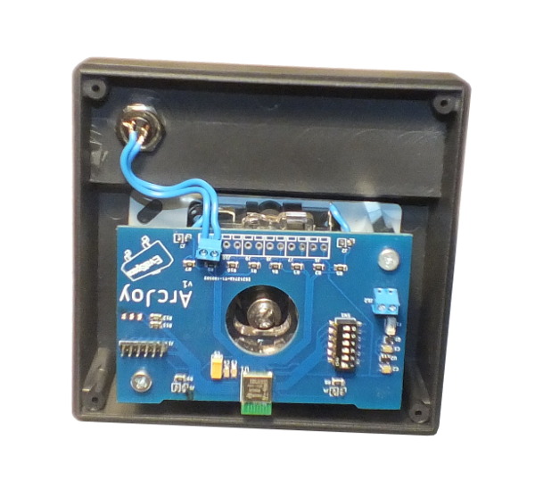
Here’s the picture of the raw case.
I don’t have a specific mechanical drawing for the joystick case preparation. I just put the PCB inside the case (as in the picture), marked centers of holes in PCB and made holes with a drill. Try to place the board to the center (in horizontal direction) of the case and in vertical direction, to board should touch the edge marked on picture below.
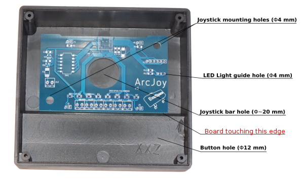
There are two mounting holes with diameter of 4 mm. They should be in centers of holes of PCB (PCB holes are slightly bigger).
LED light guide hole marker – try to use some sharp needle to mark the middle pad of three pads (those pads are for bicolor LED).
The hole for the joystick bar doesn’t have to be exactly 20 mm. I think any size from 15 mm to 28 mm should be fine. I used holesaw with the diameter of 27mm and it was ok.
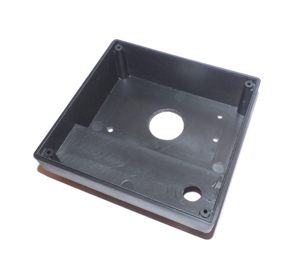
Here is how it looks like after drilling.
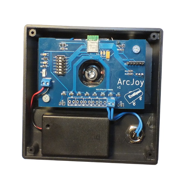
C) Solder all components to ArcJoy PCB
Using BOM or the schematic. The schematic is available here:
https://github.com/kryzysoft/ArcJoy/raw/master/ArcJoy_Pcb/ArcJoy.pdf
The hardest part is the BGA module, but it’s not as hard as it looks like. If you have hot air station, you should be fine.
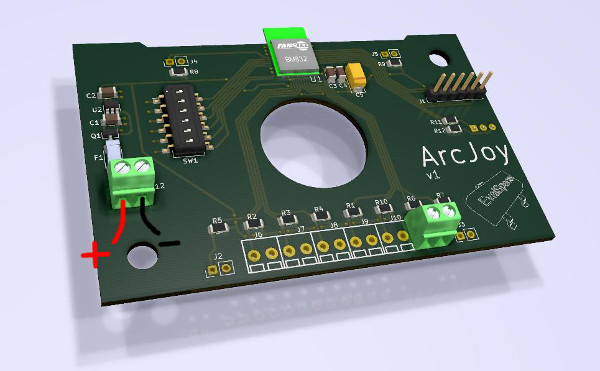
You can see that J6..J10 terminal blocks are not populated. It’s because I was thinking about more buttons in this joystick. Firmware is prepared to use those buttons, but anyway I didn’t need it.
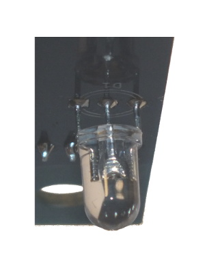
Don’t forget about bicolor led on the bottom side of the board. It should be above the board about 2,5 mm like in the picture below.
D) Upload firmware to the microcontroller on the ArcJoy board
Open ArcJoy_Prg project in Segger Embedded Studio. Connect a programmer to the board using the connector J1. I used segger J-Link integrated with NRF52840 DK board, but probably you could use other SWD programmer (like ST-LINK).
Of course you need to power up the board using the J12 connector.
Please let me know if you need any help with this. We’ll figure something out if you don’t have J-Link.
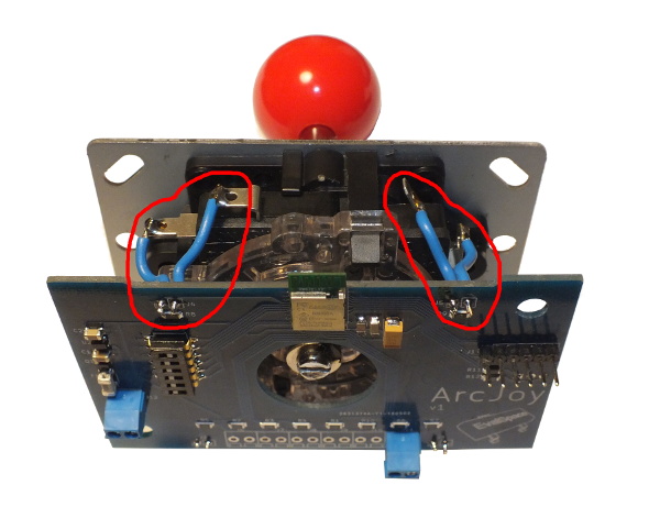
F) Connect joystick with proper pads on the board
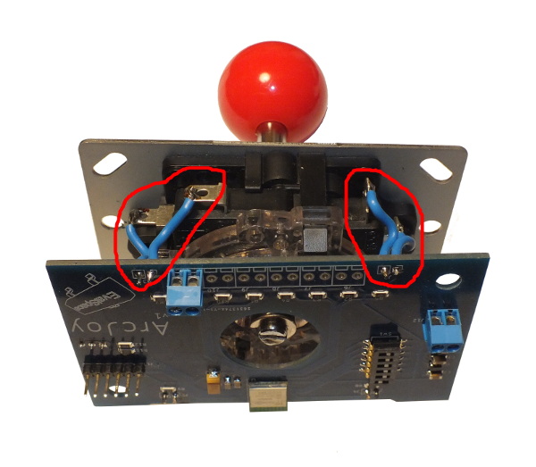
Proper pads on the board: J2, J3, J4, J5. I used 0.5mm^2 wire, but it was almost too big, so you should probably use some thinner wire. All wires should have the length about 30 mm. It should look like this:
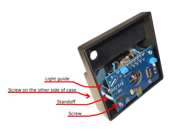
G) Mount arcade joystick in the case
Mount it using four screws, and two threaded standoffs.
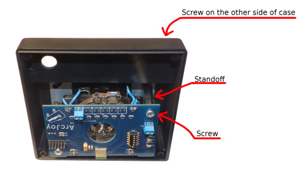
Also place the light guide in proper hole.
H) Place the button in the button hole and connect it to the terminal in PCB
I used the same wire as for the joystick connections. Wire length is 80 mm.
J) Glue a battery pack to the joystick case and connect wires
Leave some space on the left of battery pack, because it’s opening by sliding the cover to the left.
H) Upload firmware to the microcontroller on the ArcBase dongle
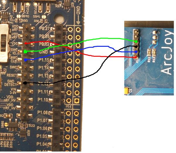
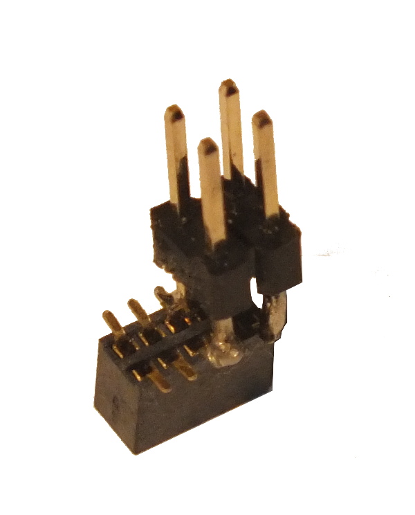
NRF52840-DONGLE doesn’t have any connector for programming, but there’s a place for the connector. I soldered the connector (1.27 mm pitch 2×5 SMD male header) there.
Now I needed also a female connector to match this one. It’s just resizing the pitch of connector from 1,27 mm to 2,54 mm.
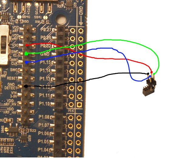
Now just connect wires to the j-link board (as in programming ArcJoy), and upload the ArcBase firmware (also using Segger Embedded Studio). Also power it up, by plugging it into USB port. Firmware is available in ArcBase_Prg folder in the github repository. Just for clarification, the RED wire in the picture below should be connected to the 1st pin of the programming connector of the dongle board.
One more thing…
If you are using two joysticks, the first switch of DIPSWITCH SW1 is for selecting which joystick is the 1’st one and which is the 2nd one (both used joysticks should have a different position on the 1st switch).
That’s all. Just put the three AAA batteries into the battery case, close the ArcJoy case, and have fun.
Thanks for reading.
If you have any questions, feel free to write a comment.